
Continuous caster lubrication: Why the grease supply matters as much as the grease
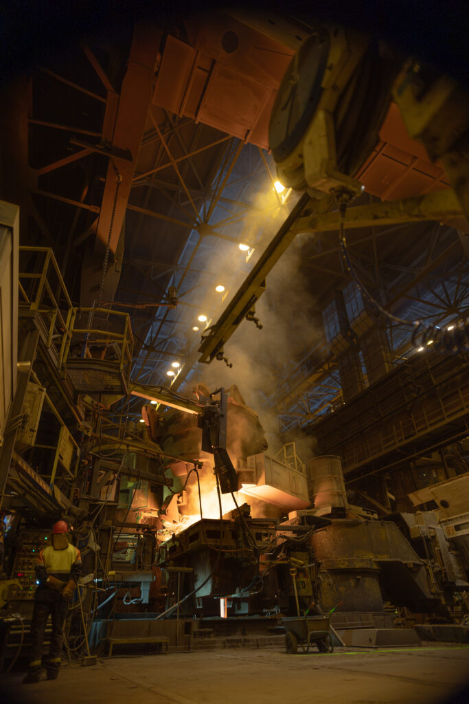
In this article, we explain why the continuous caster is the hardest place to lubricate in a steel plant, how slab, billet and bloom casters are lubricated, how much grease they consume and where relubrication-free bearings fit in.
We then follow the grease back to its container and show what changes when it arrives sealed in bulk, as it does at SSAB Raahe, where Fluid-Bags feed the centralized systems serving casting machinery.
For lubrication across the rest of the plant, see the article Steel mill lubrication: why heat, dust and water make grease supply a reliability issue.
Key facts
- A continuous caster guides the strand over some 200-300 support rolls, each running on grease-lubricated bearings.
- A typical dual-line caster system serves 300-400 lubrication points and cycles every 30-60 minutes.
- A continuous caster can consume 10-50 tonnes of grease per year; up to 280 drums of 200 liters (55 US gal).
- At SSAB Raahe, one sealed 1,000-liter (264 US gal) Fluid-Bag supplies the centralized system for about two weeks.
Why is the continuous caster so hard to lubricate?
The continuous caster combines the harshest operating conditions in the steel plant in one machine. Molten steel enters the mold at the top, and the strand then travels through some 200-300 support rolls before it is cut to length. Each roll runs on bearings that carry heavy loads at very low speeds, a combination that makes it hard to build and hold a lubricating film.
The environment makes it worse. Bearing manufacturer Timken describes the caster as one of the most challenging environments for bearings, with bearings constantly exposed to secondary cooling water spray and hard debris. Water dilutes grease and corrodes raceways. Scale works its way past seals and acts as an abrasive. Heat from the strand ages the grease and can harden it in the lines.
All this happens on a machine that rarely stops. A caster outage halts everything downstream, so maintenance teams fight to keep the strand moving between planned segment changes.
How is a continuous caster lubricated?
Most continuous casting machines use centralized grease lubrication, and the reason goes beyond convenience. In caster roll bearings, grease does two jobs: it lubricates, and it seals. A steady flow of fresh grease keeps the bearing cavity full and pushes water and scale outward before they reach the rolling elements.
A modern slab caster typically runs several separate centralized systems, each serving its own zone – segments, bender, straightener and run-out. Lubrication system maker Dropsa describes a typical caster setup as 300-400 lubrication points across 12-36 segments, running NLGI 2 grease on a cycle of 30 minutes to one hour.
Why are dual-line systems standard on continuous casters?
Dual-line systems push grease reliably over long lines to many lube points at high pressure, which suits the size and layout of a continuous caster. Each metering valve serves its points from two main lines that are pressurized alternately, so one pump can reach hundreds of bearings spread across a machine many meters long.
Dual-line systems have their own weak spots. A technical paper presented to the Brazilian metallurgy association ABM notes that grease selection for casters becomes a compromise between bearing performance and pumpability, that lines get blocked, pinched or damaged, and that used grease builds up on housings and segment frames.
Each of these problems gets worse when the grease entering the system carries air, water or particles.
How much grease does a continuous caster use?
Continuous flushing makes the caster a heavy grease user. An SKF engineering article estimates that a continuous caster can consume 10 to 50 tonnes of grease per year. The figure dates from 1994, and actual consumption depends on the number of strands, segments and lubrication points, but it shows the order of magnitude.
Translate that into containers, and the supply side comes into focus. A 200-liter (55 US gal) drum holds roughly 180 kg (400 lb) of grease. A 1,000-liter (264 US gal) Fluid-Bag holds around 900 kg (2,000 lb), depending on grease density.
Container changes per year at 10–50 tonnes of caster grease
| Annual grease consumption | 200-liter drums | 1,000-liter Fluid-Bags | Container changes avoided |
|---|---|---|---|
| 10 tonnes (22,000 lb) | approx. 55 | approx. 11 | approx. 44 |
| 25 tonnes (55,000 lb) | approx. 140 | approx. 28 | approx. 112 |
| 50 tonnes (110,000 lb) | approx. 280 | approx. 56 | approx. 224 |
Our calculation, based on approx. 180 kg per drum and 900 kg per Fluid-Bag (density approx. 0.9 kg/l). Actual figures depend on grease density and fill levels.
At the upper end, that is more than five drums a week; each one opened, connected and emptied in or near the casting hall. SSAB Raahe gives a real-world reference: one bag every two weeks means about 26 bag changes a year in place of about 130 drum changes for the same volume.
What grease is used for continuous caster segment bearings?
Caster segment bearings need grease that resists heat and water, carries heavy loads at low speed and still pumps through long dual-line systems.
According to NLGI, the most used greases in the steel industry are based on aluminium complex, lithium complex and calcium sulfonate thickeners, with specialty high-temperature and water-resistant greases for the hot and wet areas. NLGI 2 is common in caster systems, and softer grades help where long lines or cold conditions limit pumpability.
The grease choice belongs to the steel mill and its grease supplier. Whatever grease is chosen, it only performs as specified if it reaches the bearing clean.
Do continuous caster bearings still need relubrication?
Many do, but not all. Some steel producers have converted segments to sealed, relubrication-free roll units, which carry their grease fill for life. At Stahlwerke Bremen, for example, SKF reports that sealed roll units replaced continuously greased rolls in part of the roll line, while other positions on the same line still use traditional pumped grease lubrication.
Continuous grease remains the most common choice. The ABM paper cited above calls it the standard option because of its cost, and even converted casters keep centralized grease for other positions and machine areas.
For most continuous casters, the grease supply will stay a daily operational task for years to come, which makes it worth getting right.
Where can the grease supply fail between the drum and the strand?
A caster’s centralized systems are only as clean and reliable as the reservoirs feeding them. With drums, four weak points repeat with every container.
- Exposure at every change. Each new drum is opened in an environment full of steam and scale. The grease surface, pump tube and follower plate stay exposed until the pump is back in place.
- Air in the system. As a drum runs low, the pump can draw air. Air pockets in a dual-line system disturb pressure build-up and metering, and a missed lubrication cycle leaves caster bearings unprotected against water.
- Contamination multiplied. Grease cannot be filtered once it is in service. A contaminated drum does not affect one bearing, it feeds a whole zone of the caster. We explain the mechanism in the article Feeding centralized lubrication systems.
- Moisture in storage. Drums waiting near the caster breathe as temperatures shift, and humid air enters through the seals. See the article How moisture infiltrates your grease drums.
Each weak point traces back to the same root cause: the container must be opened, often, in a hostile place.
What changes when caster grease arrives sealed in bulk?
A Fluid-Bag removes the open container from the equation. The grease supplier fills the bag in a closed process, and the grease stays sealed through transport, storage and discharge.
A Discharge Roller or X-Reel stretches, rolls and squeezes the bag so the pump draws out grease steadily, without air exchange during discharge, until less than 1% remains.
For a continuous caster, four things change:
- Fewer changes. One bag replaces five drums; four fewer changeovers for every 1,000 liters (264 US gal). At 25 tonnes a year, that removes more than 100 container changes.
- No interruptions. Two bags can run side by side, so an operator changes one while the other keeps feeding the system. The centralized system never waits for a container.
- No exposure. The grease never meets the casting hall air. What the supplier filled is what reaches the reservoir.
- Less clutter. An empty bag folds flat on its wooden pallet. No stacks of empty drums near the caster, and no drum returns or cleaning.
The setup handles greases from NLGI 00 to NLGI III and works with suction-capable pumps, including the piston pumps common in grease service. The downstream system (single-line, dual-line or progressive) stays as it is.
For the full step-by-step process, read the article Bulk grease supply for steel mills: from supplier to lube pump.
How does SSAB Raahe feed its casting machinery from Fluid-Bags?
SSAB’s Raahe steel mill in Finland has handled grease with Squeeze Solution for more than 20 years. Four Discharge Rollers feed its centralized lubrication systems, including those serving casting machinery.
Before the switch, drum handling meant frequent changeovers and heavy manual work, and earlier trials with steel totes left significant grease behind. Today, the grease supplier fills the Fluid-Bags in a closed process, and the grease stays sealed until it enters the system. Bags run side by side, and slow, controlled discharge lets each 1,000-liter bag supply grease for about two weeks. One bag replaces five drums, and empty bags leave no containers to store.
Maintenance Operator Jari Haarala calls it ”the number one solution for handling grease here at SSAB Raahe.”
Read the full SSAB Raahe case >>
Another case study
Friedr. Lohmann, a German producer of high-performance steels and castings, runs the same setup with a semi-automatic Discharge Roller feeding its centralized lubrication system. In a dust-heavy plant, the sealed system keeps the grease clean and residual waste below 1%.
”On a continuous caster, the centralized systems run day and night, and they pump a lot of grease. Every drum change is a moment where water, scale or air can get in, and with tonnes of grease a year, those moments add up. With bags running side by side, the system never waits and the grease never sees the casting hall.” – Magnus Berglund, CCO, Squeeze Solution (Fluid-Bag Ltd.)
How can you evaluate your caster’s grease supply?
A short review often reveals more than expected. We suggest four steps:
- Map the systems. List every centralized system on the continuous caster, the grease it runs and its annual consumption.
- Count the changes. Convert consumption into containers per month, and note who changes them, where and how long the grease sits exposed.
- Follow the refill. Watch one complete drum change. Look for open lids, pump tubes on the floor and the point where the drum runs low.
- Check the history. Compare lubrication alarms, air in the lines and bearing failures against changeover times.
If consumption runs into tonnes and changes happen weekly, the supply format deserves the same attention as the grease specification.
For a cost view, read the article The total cost of grease drum ownership nobody calculates.
FAQ: Grease supply for continuous casters
How many lubrication points does a continuous caster have? A typical slab caster dual-line system serves 300-400 lubrication points across 12-36 segments, according to lubrication system maker Dropsa. The number depends on caster type, strand count and roll design.
How often does a caster’s centralized system cycle? Typical cycles run every 30 minutes to one hour. The interval depends on the grease, the bearing design and the operating conditions in each zone.
Can Fluid-Bags feed dual-line centralized systems? Yes. The Fluid-Bag feeds the pump, and the pump feeds the system. Single-line, dual-line and progressive systems all run with Fluid-Bag supply. The connection, directly to the system pump or via a transfer pump to the reservoir, depends on the setup.
Which caster greases can be handled in Fluid-Bags? Greases from NLGI 00 to NLGI III. Greases above NLGI 0 normally use a 3-inch outlet.
How do we handle high grease consumption? Run several discharge machines and connect bags side by side. SSAB Raahe uses four Discharge Rollers across its centralized systems.
How are full bags stored near the caster? Filled bags on wooden pallets stack two high and stay sealed until discharge.
Keep the caster’s grease as clean as the day it was made
Continuous caster lubrication already demands careful choices: high-temperature greases, robust seals, separate centralized systems for each zone. Those choices assume that clean grease enters the reservoir. With tonnes of grease a year arriving in drums, that assumption gets tested hundreds of times – every time a lid comes off near the strand.
A sealed bulk supply removes most of those moments and makes the rest routine. SSAB Raahe has fed casting machinery this way for years, and Lohmann does the same in a dust-heavy plant.
Want to see what it would mean for your caster? Book a no-obligation video meeting, and we will map your caster’s grease consumption to container changes together. If it makes sense, we can help with a test, installation and training for your team.
This article draws on our work with SSAB Raahe and Friedr. Lohmann and on the sources linked in the text. Container figures are our own calculations, as noted under the table. Written by the Squeeze Solution team.
The courage to [[squeeze through]]
Innovation meets resistance. And since 1984, we’ve been helping companies challenge the status quo and find better ways to handle liquids and semi-solids.
Our solution serve manufacturers and end-users across industries and products: adhesives, sealants, coatings, inks, lubricants, cosmetics, foods, pharmaceuticals, and more.
Maximal squeeze for minimal waste. Let’s pioneer together.
